
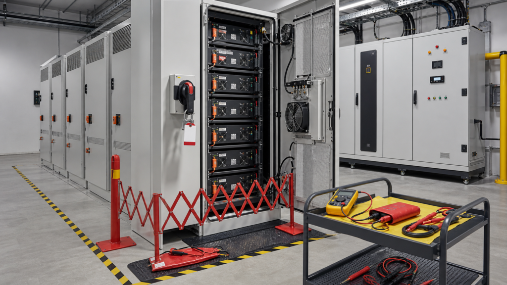
Isolating one lithium battery rack for maintenance is a system operation, not a single-switch action. Energy may remain in cells, DC bus capacitors, parallel racks, the power-conversion system, auxiliary supplies, communication circuits, or externally connected sources. A contactor-open indication can be useful status information, but it is not by itself proof that the work zone is de-energized.
A defensible procedure identifies the exact maintenance boundary, every source and backfeed path, the devices that provide physical isolation, stored-energy discharge behavior, lockout authority, voltage-test points, BMS and PCS response, temporary bypass limits, and the tests required before return to service. This article is a procurement and engineering framework; the site owner must apply local law, equipment instructions, qualified-person requirements, and an approved electrical-safety program.
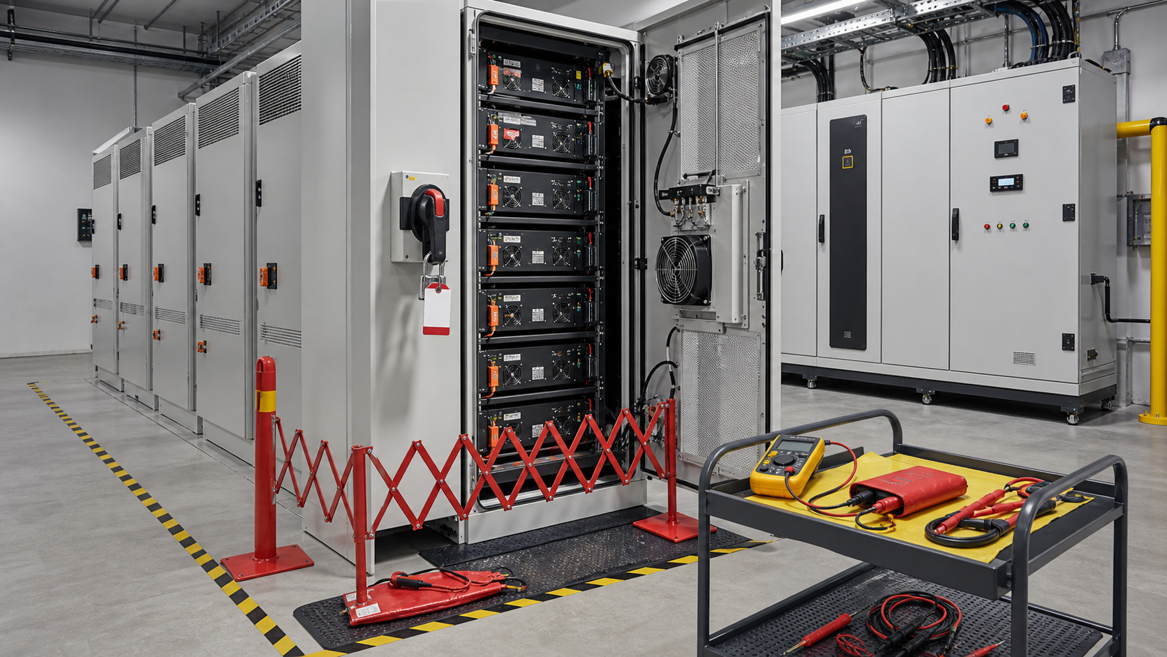
1. Draw the energy-isolation boundary
Begin with a current as-built single-line diagram and rack interconnection drawing. Mark cell strings, module service disconnects, rack contactors, fuses, manual disconnects, common DC bus, precharge circuit, PCS DC link, auxiliary AC/DC supplies, HVAC, fire-detection interfaces, UPS circuits, grounding, communications, and any PV, generator, grid, or adjacent storage connection. Identify energy that can cross the planned work boundary in either direction.
OSHA's 29 CFR 1910.147 control-of-hazardous-energy standard requires documented procedures for shutdown, isolation, blocking or securing, lock placement and removal, and verification of energy-control effectiveness where the standard applies. Local regulations may differ, and electrical work can invoke additional rules. The transferable engineering lesson is that every hazardous source and stored-energy mechanism must be controlled and verified.
-
Normal rack cell voltage and maximum possible open-circuit voltage at the service boundary.
-
Available fault current from the isolated rack and from parallel racks or the PCS side.
-
DC-link and filter-capacitor discharge time, residual-voltage test point, and possibility of reaccumulation.
-
Auxiliary supplies that can keep contactors, cooling, heaters, BMS modules, or remote I/O energized.
-
Communication or remote-control paths that could issue a close, precharge, charge, or discharge command.
-
Mechanical, thermal, chemical, and gravity hazards that remain after electrical isolation.
2. Distinguish control state from physical isolation
A BMS command to open contactors is part of orderly shutdown, but contactor position feedback can be wrong, contacts can weld, and voltage can arrive from another source. The maintenance design should provide a lockable energy-isolating device or another approved method at the work boundary, together with accessible test points. The approved procedure must state which devices are control functions and which devices establish isolation.
Do not withdraw connectors under load unless the connector and procedure expressly permit it. Do not assume a fuse creates isolation after normal shutdown. Do not rely on an HMI screen as the only indication. Where capacitors discharge automatically, verify the actual residual voltage after the specified time; a timer alone is not an absence-of-voltage test.
3. Use a written shutdown and lockout sequence
-
Authorize the work: define scope, rack ID, affected loads, operating constraints, responsible person, qualified workers, permit number, and expected duration.
-
Stabilize the system: stop charge or discharge through the normal controls, confirm current approaches the approved threshold, and capture alarms, state of charge, temperatures, and firmware/configuration identity.
-
Open controlled devices: command rack contactors and PCS interfaces in the documented sequence; confirm status but do not treat status as isolation proof.
-
Operate energy-isolating devices: isolate every identified source and apply personal or group locks and tags according to the site procedure.
-
Control stored energy: wait the documented discharge period, block mechanical movement, and address thermal or pressure hazards that can reappear.
-
Verify absence of voltage: use an adequately rated tester and the approved test method at every defined point; verify the tester before and after the measurement.
-
Establish the work zone: install barriers, covers, signage, environmental controls, and emergency arrangements before opening modules or exposed compartments.
The sequence must cover shift changes, contractor coordination, emergency lock removal, interrupted work, and changes in scope. OSHA's lockout/tagout overview emphasizes procedures, training, and control of hazardous-energy release. It should not be treated as a substitute for the battery manufacturer’s service manual or the electrical requirements applicable at the site.
4. Engineer the temporary bypass as an abnormal operating mode
In this context, bypass means operating the ESS with one rack unavailable or using an approved alternate path. It must never mean defeating protective functions to make alarms disappear. Removing a rack can change total capacity, allowable power, current sharing, fault current, SOC estimation, thermal loading, redundancy, and PCS operating limits. The EMS and BMS must recognize the rack as intentionally unavailable rather than repeatedly trying to reconnect it.
Assume eight equal racks normally support a 400 kW discharge limit, or 50 kW per rack. Removing one rack does not automatically justify 400 kW from seven racks; that would require about 57.1 kW per rack, a 14.3 percent increase. The temporary limit must come from the approved rack current, SOC, temperature, bus design, PCS controls, aging spread, and manufacturer instructions. The arithmetic only exposes the change; it does not set the permissible power.
-
Permit owner and expiry time for the bypass state.
-
Maximum charge and discharge power, SOC window, temperature range, and minimum number of healthy racks.
-
Alarms that must remain active and the unmistakable HMI indication that redundancy is reduced.
-
Inspection frequency for current imbalance, connector temperature, rack voltage spread, and cooling performance.
-
Automatic stop conditions, including loss of another rack, communication fault, overtemperature, unexpected current sharing, or permit expiry.
-
Restoration steps and independent confirmation that no jumper, software force, or temporary parameter remains.
5. Coordinate BMS, PCS, EMS and fire-safety interfaces
Rack isolation changes more than DC power. The PCS may need a revised current limit; the EMS may need reduced available energy; the fire-safety system may monitor rack communications; HVAC control may depend on rack status; and remote operators need an alarm that distinguishes planned maintenance from a fault. Test loss of rack communication and ensure local protective functions remain effective.
The U.S. Department of Energy's Energy Storage System Guide for Compliance with Safety Codes and Standards organizes ESS safety across equipment, installation, operation, and maintenance requirements. It is a reference map, not evidence that a particular product complies. Certification and code claims must be verified against the actual model, installation, current editions, and authority having jurisdiction.
6. Maintenance isolation acceptance matrix
-
Normal shutdown: current decays as specified; rack contactors open; PCS and EMS show the correct planned state; no unexpected trip of healthy racks.
-
Backfeed challenge: with the rack isolated, test approved points for voltage from the common bus, auxiliary supplies, PCS, and adjacent circuits.
-
Stored-energy interval: record voltage versus time at the defined test point and verify the safe-work threshold using the approved instrument and procedure.
-
Communication loss: disconnect or simulate the isolated rack link; confirm deterministic alarms, power derating, and no automatic close command.
-
Second-rack fault during bypass: confirm the system reaches the defined safe state rather than exceeding remaining-rack limits.
-
Return to service: verify polarity, insulation or continuity tests as applicable, contactor state, precharge, communication identity, alarm reset, current sharing, and thermal behavior.
-
Permit closure: remove temporary settings and software forces, reconcile locks and tools, update drawings and maintenance history, and obtain operations acceptance.
Record actual values, not only pass/fail. Useful fields include rack and module serial numbers, SOC, open-circuit voltage, bus voltage, discharge time, tester ID, temperatures, insulation result where applicable, precharge duration, contactor feedback, communication status, rack current after reconnection, alarm timestamps, deviations, and signatures.
7. Procurement and supplier review
A buyer should request the rack-level single line, isolation boundary, fault-current basis, disconnect and fuse ratings, contactor and precharge logic, residual-energy behavior, service test points, BMS/PCS/EMS interface description, maintenance manual, lockout provisions, required PPE basis, spare-parts strategy, and return-to-service matrix. Ask the supplier to identify which bypass modes are supported and which actions invalidate safety evidence or warranty.
Configuration control matters because a firmware or parameter change can alter shutdown, precharge, communication timeout, and automatic reconnection. The BMS firmware update and rollback guide covers controlled recovery, while the BMS HIL fault-injection matrix provides a framework for challenging control sequences before site work. Maintain serial and revision traceability using the battery-pack traceability guide.
Do not claim that a rack, bypass, or field modification is certified merely because individual components carry marks. Verify the complete system scope, installation instructions, approved configurations, and destination requirements. Supplier documentation should state assumptions and deviations rather than shifting integration decisions to the technician at the open cabinet.
Frequently asked questions
Is opening the battery rack contactor sufficient isolation?
No. A contactor is a control device and may not provide a visible, lockable, verified isolation boundary. The approved design must identify every source, isolation device, stored-energy hazard, backfeed path, and absence-of-voltage test point.
Can one battery rack be bypassed while the rest of the ESS operates?
Only when the system architecture, manufacturer instructions, risk assessment, protection settings, current sharing, thermal limits, communications, and operating permit explicitly allow that state. Reduced redundancy and altered fault behavior must be documented.
What must be checked before returning an isolated rack to service?
Confirm work completion, tool and barrier removal, correct rack identity, connector and polarity checks, insulation and voltage checks as applicable, BMS compatibility, precharge, communication, alarms, current sharing, thermal response, and formal permit closure.
Contact FISSION Lithium
For industrial LiFePO4 battery-pack engineering, BMS integration, ESS rack documentation, validation planning, OEM samples, and quotations, contact FISSION Lithium / Zhejiang Feixiang Technology Co., Ltd.
Email: [email protected]. Phone / WhatsApp / WeChat: +86 18969667183. Website: www.zjfx-tech.com.