
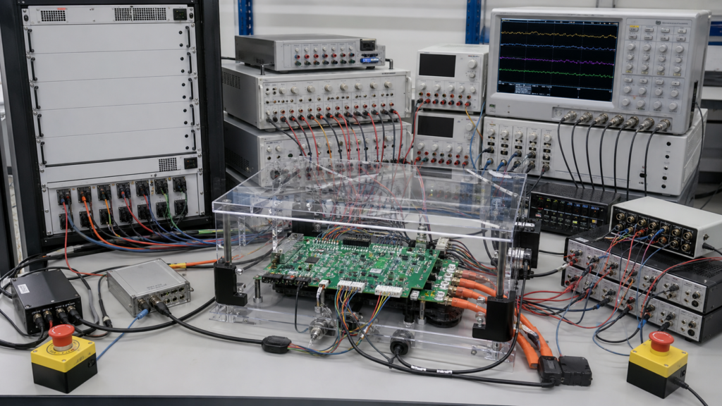
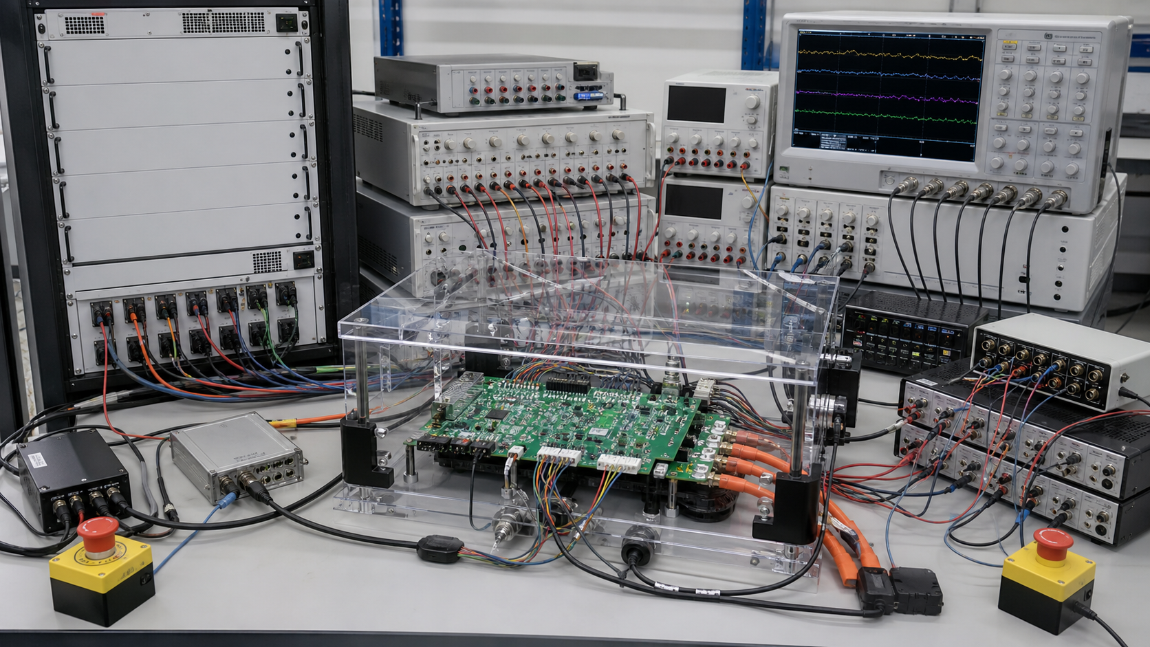
BMS hardware-in-the-loop fault-injection testing connects the production-intent battery management controller to a real-time simulator that emulates cells, current, temperature, contactors, chargers, vehicle or equipment interfaces, and communications. Engineers can then introduce controlled faults and measure the BMS response without deliberately damaging a complete lithium battery pack. The method is powerful because the same stimulus, timing, software build, and acceptance rule can be repeated after every change.
HIL does not prove cell safety, enclosure strength, thermal propagation behavior, or every high-energy interaction. It verifies the controller hardware, embedded software, I/O, diagnostic logic, state transitions, and communication behavior within the validated limits of the simulator. A credible program therefore links each test to a requirement, identifies what the model can and cannot represent, correlates critical cases against physical evidence, and retains machine-readable logs for release decisions.
1. Define the HIL boundary before counting test cases
The test boundary states which real components are present and which are simulated. A controller-level bench may use the actual BMS master and slave boards while emulating cell voltages, pack current, thermistors, isolation monitor, contactor coils, charger, inverter, key switch, interlocks, CAN, and RS485. A higher-level rig may include real contactors and a protected low-voltage load. The boundary determines which failures can be claimed as tested.
-
List every physical device under test, hardware revision, bootloader, application software, calibration file, and parameter-set checksum.
-
Map each simulated channel to its BMS pin, electrical range, resolution, update rate, latency, isolation method, and overvoltage protection.
-
Define the real-time plant model: cell equivalent circuit, state-of-charge and temperature dependence, current sensor behavior, thermal lag, contactor feedback, charger response, and equipment messages.
-
State excluded physics, including high-energy arcing, cell venting, enclosure pressure, coolant leaks, connector heating, crash loads, and electromagnetic immunity unless separately reproduced.
-
Identify bench safety functions: current limiting, galvanic isolation, emergency stop, watchdog, output clamps, safe power-down, and recovery after host or simulator failure.
NASA's product verification guidance describes verification testing as controlled, instrumented evidence that an element meets allocated requirements and explicitly includes hardware-in-the-loop testing. That principle matters to buyers: the deliverable is not a video of a fault appearing on a screen, but a traceable result tied to an approved requirement, configuration, procedure, and report.
2. Build fault cases from hazards, interfaces, and field evidence
Start with the product requirements, interface control document, failure-mode analysis, hazard analysis, diagnostic specification, and known field failure modes. Each fault needs a physical meaning. An arbitrary signal step that cannot occur in the harness or sensor may test code robustness, but it should not be presented as validation of a realistic failure. Conversely, only testing clean open circuits misses intermittent contacts, drift, bounce, common-mode faults, and timing races.
-
Cell-voltage inputs: open wire, short to adjacent channel, stuck value, offset drift, noise, implausible rate of change, channel swap, and one weak-cell trajectory during charge or discharge.
-
Temperature inputs: open and short circuit, slow drift, local hot sensor, implausible gradient, frozen value, intermittent connector, and disagreement between redundant sensors.
-
Current and isolation signals: offset, gain error, saturation, reversed polarity, dropout, noisy zero crossing, isolation-resistance decline, and diagnostic communication loss.
-
Power-path control: welded contactor feedback, contactor command without closure, precharge timeout, precharge resistor anomaly, feedback bounce, charger present at an invalid time, and unsafe wake or shutdown sequence.
-
Communications: missing frame, wrong counter, checksum error, stale payload, bus-off, duplicate ID, delayed frame, burst loss, high bus load, malformed diagnostic request, and inconsistent commands from charger and equipment controller.
-
Power and timing: brownout, rapid key cycling, loss of auxiliary supply during write, watchdog reset, clock drift, processor overload, interrupted firmware update, and recovery with latched or active faults.
For industrial lithium applications, the applicable compliance basis depends on the product and destination. The official IEC 62619 overview covers safety requirements and tests for secondary lithium cells and batteries used in industrial applications. HIL evidence can support verification of BMS-controlled functions, but it does not by itself establish compliance with IEC 62619 or any other standard. The certification plan must identify which clauses require cell, module, pack, environmental, abuse, or independent laboratory testing.
3. Use a requirements-to-test matrix
A requirements-to-test matrix prevents a large automated suite from creating false confidence. One row should represent one verifiable behavior and contain: requirement ID; hazard or function; initial BMS state; software and calibration version; simulated plant version; injected fault; injection point and waveform; expected detection condition; maximum response time; required control action; diagnostic code and persistence; recovery rule; logged signals; test level; result; deviation ID; and reviewer.
Consider a cell overvoltage protection requirement. The matrix should not say only "inject high voltage and expect a trip." It should state the starting state of charge, charge current, threshold and hysteresis from the approved calibration, voltage ramp rate, measurement-filter behavior, debounce time, permitted detection window, contactor or charger command, diagnostic message, latch behavior, and restart condition. Sweep values immediately below, at, and above the decision boundary so the test proves both activation and non-activation.
Worked timing acceptance example
Assume the approved requirement says the BMS must issue a charge-disable command within 100 ms after a validated fault condition becomes true. The HIL injection timestamp uncertainty is +/-2 ms and the CAN capture uncertainty is +/-1 ms. A run measures 94 ms from the commanded fault boundary to the first valid charge-disable frame. A conservative upper bound is 94 + 2 + 1 = 97 ms, so this run passes the 100 ms requirement. A measured 98 ms would have an upper bound of 101 ms and should not be declared a clean pass without the project's predefined uncertainty rule.
This arithmetic is illustrative; the actual limit, uncertainty method, confidence level, sample count, and worst-case operating conditions must be defined by the product requirements and measurement plan. Store raw timestamps, not only a rounded report value. Include simulator step size, I/O update period, network capture method, clock synchronization, trigger definition, and any software filtering so another engineer can reproduce the result.
4. Validate signal fidelity and timing before fault campaigns
A fault suite is only as trustworthy as the bench. Calibrate cell-voltage, current, temperature, isolation, digital, PWM, and communication channels against traceable reference instruments across the range used by the tests. Record gain, offset, noise, bandwidth, update rate, saturation, and latency. Verify that output protection does not distort the injected waveform in a way that makes the test easier than the physical fault.
The research paper Hardware-in-the-Loop Test of Battery Management Systems describes a HIL system intended for comprehensive BMS component testing. A separate study on BMS fault-response performance focuses on accuracy, timeliness, and reliability under faults such as overcharge, overdischarge, overtemperature, and overcurrent. These are useful design references, but a supplier must still correlate its own simulator, model, controller, and acceptance criteria.
-
Static correlation: compare commanded and measured channel values at low, middle, threshold-adjacent, and high points.
-
Dynamic correlation: compare ramp, step, noise, dropout, and intermittent-fault waveforms at the BMS pins, not only inside the simulator software.
-
Timing correlation: measure command-to-pin, pin-to-detection, detection-to-output, and output-to-message delays with a common clock or characterized synchronization.
-
Model correlation: compare selected state-of-charge, state-of-health, thermal, current, and fault cases with physical bench or pack data within a defined domain.
-
Repeatability: run the same case across days, operators, bench restarts, and software builds; investigate spread before setting tight acceptance limits.
5. Exercise sequences, not isolated thresholds
Many serious defects appear during transitions: sleep to wake, precharge to run, charging to fault, regenerative current to shutdown, or firmware update to power loss. A threshold test can pass while the surrounding state machine behaves incorrectly. Test sequences should combine operating states, boundary values, communication timing, and a second fault. For example, inject a thermistor intermittent fault during charging while charger messages are delayed, then verify the system chooses the intended safe action and records both conditions without losing the first event.
Use deterministic scripts for release tests and randomized or combinatorial campaigns for discovery. Random testing must remain reproducible through a saved seed, stimulus file, initial state, and environment version. Avoid claiming coverage from the number of cases alone. Report requirement coverage, state and transition coverage where available, boundary coverage, fault classes, interface coverage, and untested hazards. A failed automated assertion should preserve pre-trigger and post-trigger data rather than immediately resetting the bench.
6. Set release gates and supplier deliverables
For OEM procurement, the HIL package should be a controlled engineering deliverable. Request the bench architecture, I/O map, calibration certificates, model description and validity range, requirements matrix, source-controlled scripts, software and parameter fingerprints, raw-data format, automated report, failure triage process, correlation report, known limitations, and rerun policy. Define which artifacts the customer receives and which remain available for witnessed testing or audit.
Where the BMS controls safety-related machinery functions, the project team should determine whether machinery functional-safety standards apply. ISO 13849-2 specifies validation by analysis and testing for safety-related parts of control systems designed under ISO 13849-1. Referencing that standard is not a claim that a battery pack or BMS has achieved a performance level; it is a reminder that safety claims require an application-specific architecture, analysis, validation plan, and documented evidence.
-
Block release when a safety requirement has no approved test, analysis, or justified alternative verification method.
-
Block release when HIL scripts reference obsolete I/O, firmware, parameters, CAN databases, or model versions.
-
Require root cause, corrective action, regression selection, and documented closure for every failed safety-critical test.
-
Rerun affected cases after BMS hardware, firmware, bootloader, calibration, harness, contactor, charger, vehicle interface, or model changes.
-
Archive the exact passing configuration and link it to production traceability so field logs can be interpreted against the released behavior.
The internal guide to BMS firmware update rollback and power-loss recovery expands the update and recovery cases. For release-data continuity, also review battery pack traceability from cell lot through BMS firmware. These links should feed the same configuration ledger rather than separate spreadsheets with conflicting versions.
Frequently asked questions
Can HIL testing replace physical lithium battery pack testing?
No. HIL is well suited to repeatable BMS controller, software, I/O, communication, diagnostic, and timing verification within the simulator's validated domain. It cannot replace required cell, module, pack, thermal, mechanical, environmental, abuse, high-energy, or certification tests.
What should a BMS fault-injection test record?
Record the requirement ID, initial state, hardware and software versions, calibration and model versions, exact injected waveform, timestamps, measurement uncertainty, expected response, observed control action, diagnostics, raw signals, result, deviation, and reviewer.
How often should the BMS HIL regression suite be rerun?
Run the affected regression set after any change to BMS hardware, firmware, bootloader, calibration, I/O, communication database, contactors, charger or equipment interface, test model, or test bench. Run the approved release suite against the exact production-intent configuration before release.
Contact FISSION Lithium
For industrial LiFePO4 battery pack requirements, BMS interface coordination, validation documentation, samples, OEM projects, and quotations, contact FISSION Lithium / Zhejiang Feixiang Technology Co., Ltd. Provide the application, voltage and capacity, peak and continuous current, charger and equipment interfaces, communication protocol, environment, quantity, destination market, and required standards.
Email: [email protected]. Phone / WhatsApp / WeChat: +86 18969667183. Website: www.zjfx-tech.com.