
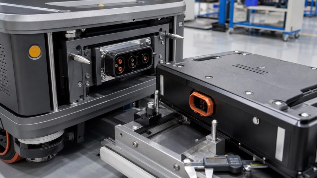
A blind-mate battery connector is not self-aligning simply because its housing has a lead-in chamfer. In an AGV battery exchange, the vehicle, removable pack, guides, lift mechanism, connector bracket, and electrical contacts form one tolerance chain. Misalignment can bend contacts, overload the housing, prevent full engagement, damage seals, increase contact resistance, or create an intermittent interlock. The engineering task is to make mechanical guidance absorb positional error before the power contacts carry load.
ISO 3691-4:2023 addresses safety requirements and verification for driverless industrial trucks and their systems, including automated guided vehicles. It does not replace connector design work, but it reinforces a lifecycle view of foreseeable conditions, operating zones, maintenance, and verification. For the connector itself, IEC 61984:2008 specifies safety requirements and tests for connectors within its scope. The applicable product standard, connector detail specification, vehicle risk assessment, battery standard, and local requirements must be identified for the actual voltage, current, environment, and market.
Separate guidance from electrical engagement
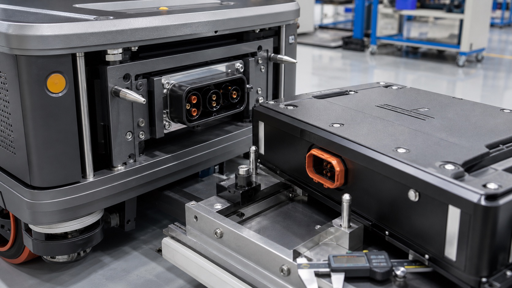
The docking structure should establish datums in a deliberate sequence. Coarse rails or rollers first capture the battery pack. Tapered guide pins or funnels then reduce lateral and angular error. A compliant connector mount absorbs the final small residual displacement. Only after those mechanical stages should protective earth, interlock, auxiliary, precharge, and main power contacts engage in the specified order.
Do not use the power contacts as alignment pins. Contact beams are designed to produce a controlled normal force over an allowed engagement path, not to correct an uncontrolled battery carrier offset. The connector manufacturer must provide the permissible X, Y, and Z displacement, pitch, yaw, roll, engagement stroke, force profile, float travel, mating cycles, and mounting-flatness limits. Keep those limits in the interface control drawing rather than in an email or sales slide.
The floating half needs both travel and a defined neutral return. Too little compliance transfers shock to the contacts. Too much compliance can let the connector droop, oscillate, or begin engagement at an angle. Cable stiffness, busbar reaction, coolant hoses, and enclosure seals can consume the available float travel. Measure the assembled system, not an unloaded connector on a bench.
Worked tolerance stack
Assume the lateral X-axis contributors at the connector plane are AGV docking repeatability of plus or minus 1.5 mm, battery carrier location of plus or minus 0.8 mm, and connector bracket position of plus or minus 0.5 mm. A conservative arithmetic worst-case stack is:
1.5 + 0.8 + 0.5 = 2.8 mm.
If the contributors are independent, centered, and statistically characterized, the root-sum-square estimate is:
sqrt(1.5 squared + 0.8 squared + 0.5 squared) = 1.77 mm.
Neither result is automatically acceptable. The 2.8 mm value describes a possible dimensional envelope, while 1.77 mm is a statistical estimate that depends on assumptions and process capability. Compare the selected design basis with the connector manufacturer's allowable capture window after subtracting wear, thermal expansion, frame deflection, contamination, assembly drift, and measurement uncertainty. If the allowable window is not documented, do not invent it.
Repeat the calculation for Y and Z, then convert angular errors to displacement at the contact plane. For example, a small yaw at a long distance between the battery datum and connector can produce more lateral error than the connector bracket tolerance itself. A three-dimensional stack should identify each datum, sign convention, distribution assumption, temperature, load case, and owner. The production drawing must state where each dimension is measured.
Electrical engagement sequence
The intended sequence should be both mechanically designed and electrically monitored. A typical architecture may establish protective bonding first, then detect position or interlock, connect auxiliary circuits, complete precharge, and finally close contactors for the main current path. The exact sequence depends on the system and connector. A blind-mate interface should not routinely make or break the main battery current unless it is specifically rated and validated for that duty.
Precharge limits inrush into the AGV DC link before the main contactors close. The BMS and vehicle controller should verify voltage convergence, connector position, interlock continuity, polarity, isolation status where applicable, and contactor state. If the pack stops partially mated, the control logic should keep hazardous energy isolated and report a diagnostic that distinguishes alignment failure from precharge timeout or communications loss.
Coordinate this interface logic with BMS hardware-in-the-loop fault injection testing. Inject open interlock, welded contactor indication, delayed auxiliary contact, interrupted communication, excessive precharge time, and position-sensor disagreement. The test should verify the commanded safe state and the diagnostic record, not merely that an alarm appears.
Alignment and engagement test matrix
Build a fixture that can set controlled offsets at the connector plane. It should cover X, Y, Z, pitch, yaw, roll, engagement speed, temperature, cable reaction, pack mass, and representative guide wear. Record actual values and uncertainty. A practical matrix includes:
-
Centered baseline: measure engagement force versus stroke, contact sequence, interlock transition, contact resistance, and housing movement.
-
Positive and negative X/Y limits: verify guide capture, no contact-side loading beyond limits, complete latch or seating, and stable electrical measurements.
-
Z stroke limits: test short insertion, overtravel prevention, full seating detection, and safe response to a blocked pack.
-
Angular corners: combine pitch or yaw with lateral offset because single-axis tests can miss edge interference.
-
Contamination: introduce the approved dust or debris challenge at defined mass and location; never scatter uncontrolled workshop dirt and call it repeatable.
-
Temperature extremes: condition the pack, vehicle frame, connector, and cables to relevant limits so differential expansion and stiffness are represented.
-
Dynamic approach: measure peak force and rebound at minimum, nominal, and maximum docking speed, including foreseeable controller overshoot.
-
Partial mate: stop at defined strokes and verify that main energy remains isolated, the interlock diagnosis is correct, and recovery does not scrape live contacts.
IEC 60512-9-3:2011 defines a method for assessing mechanical and electrical operational endurance through engagement and separation cycles with a specified electrical load. The project must determine whether that method, IEC 60512-9-1 mechanical operation testing, a connector detail specification, or another applicable method fits the actual connector and switching duty. State cycle count, electrical load, speed, rest period, atmosphere, temperature, inspection intervals, and failure criteria.
At each interval, inspect guide pins, funnels, compliant mount, connector housing, seals, terminals, latches, cable strain relief, and fasteners. Measure engagement force, float return, contact resistance using an appropriate low-resistance method, insulation where applicable, and temperature rise at rated duty. Trend values by cycle; a final pass/fail result can hide progressive wear.
Fault tree for incomplete mating
Start a fault tree with the top event “battery not fully and safely connected.” Mechanical branches include battery skew, damaged guide, foreign object, loose bracket, depleted float travel, cable reaction, enclosure deformation, worn rollers, and incorrect pack variant. Electrical branches include open interlock, failed position sensor, precharge timeout, contactor feedback mismatch, damaged auxiliary contact, high contact resistance, or communication loss. Control branches include wrong sequence, stale state, inadequate timeout, and an unsafe retry routine.
For each cause, define detection, safe response, service evidence, and prevention. A technician should be able to distinguish a dirty guide from a BMS fault without repeatedly forcing the pack. Record alignment measurements, connector cycle count, fault codes, photographs, replaced components, and post-repair verification. If the BMS enters undervoltage protection during a prolonged fault, use a documented recovery strategy such as the considerations in AGV battery low-voltage recovery; never bypass protection simply to complete docking.
Production and procurement controls
The buyer's interface specification should include connector part numbers, keying, polarity, rated voltage and current, contact sequence, communication pins, shielding, sealing, mounting datums, fastener torque, float travel, guide geometry, engagement speed, force limits, environmental conditions, and required evidence. Define which organization owns the vehicle-side half, battery-side half, mating compatibility, and change approval.
Freeze the approved connector, terminals, plating, cable or battery busbar creepage and clearance geometry, bracket, guide pins, compliant mount, sensors, firmware parameters, labels, and assembly process. Require written notice before changing a connector supplier, plating specification, terminal crimp, plastic resin, lubricant, cable length, mounting tolerance, or firmware threshold.
Production records should link a battery serial number to connector lot, terminal and cable lots, crimp or busbar process, torque records, end-of-line engagement check, electrical test, firmware, and nonconformities. A go/no-go fixture may screen datum position, but it does not replace periodic force-stroke measurement and tolerance studies. Packaging must restrain the pack without loading the connector and must protect guide and contact surfaces from impact and contamination during transport.
Before supplier approval, ask for drawings, declared standards, test reports, calibration traceability, measurement-system analysis, process capability for critical datums, endurance data, change-control procedure, and failure-analysis examples. Verify that reports identify the tested connector, mounting arrangement, specimens, conditions, equipment, limits, and results. Do not infer AGV system compliance from a connector certificate or a battery brochure.
FAQ
How much misalignment can a blind-mate AGV battery connector accept?
Only the connector manufacturer's documented capture and operating envelope answers that question. Compare it with the complete X/Y/Z and angular tolerance stack, then subtract margin for wear, temperature, deflection, contamination, and measurement uncertainty.
Should the connector contacts align the battery pack?
No. Coarse guides, tapered features, and structural datums should capture the pack before contact engagement. A compliant connector mount should absorb only the defined residual error so electrical contacts are not used as structural alignment pins.
What should be measured during endurance testing?
Record cycle conditions, engagement force versus stroke, guide and housing wear, compliant-mount return, contact resistance, insulation where applicable, temperature rise, interlock timing, precharge sequence, fastener condition, and every failure or adjustment.
What should an OEM buyer freeze after sample approval?
Freeze connector and terminal part numbers, plating, keying, cable or busbar interface, brackets, guides, compliant mount, sensors, firmware thresholds, drawings, critical tolerances, assembly processes, test methods, labels, and packaging under written change control.
Contact FISSION Lithium
For industrial LiFePO4 AGV battery packs, BMS integration, connector-interface review, samples, and validation planning, contact FISSION Lithium / Zhejiang Feixiang Technology Co., Ltd. Email: [email protected]. Phone: +86 18969667183.