

BMS Thermistor Placement and Temperature-Coverage Validation
BMS thermistor placement is the engineering process of choosing sensor locations that represent the hottest, coldest, and most safety-relevant regions of a battery pack across normal operation and credible faults. A good design does not simply attach one NTC sensor to every few cells. It proves, through mapped testing, that the measured temperatures bound or predict critical unmeasured locations with known error and response time.
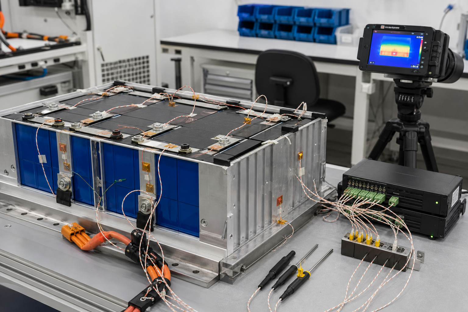
Industrial LiFePO4 packs for forklifts, AGVs, stationary storage, and mobile equipment experience nonuniform heating from cell impedance, busbar joints, contactors, fuses, cooling paths, enclosure boundaries, and unequal airflow or coolant flow. The National Renewable Energy Laboratory paper Li-Ion Battery Thermal Characterization for Thermal Management Design reports that pack-level testing can reveal considerable temperature nonuniformity and that module interconnects add heat that cell-only characterization can miss. That is why sensor coverage must be validated at pack level.
The applicable safety framework must also be defined. IEC 62619:2022 specifies safety requirements and tests for secondary lithium cells and batteries used in industrial applications, including stationary systems, forklifts, and AGVs. A buyer should identify the applicable edition, market requirements, product scope, and contractual tests rather than claiming compliance from thermistor count alone.
Begin with thermal risk locations
Create a thermal-risk map before deciding sensor quantity. Use cell and component data, current paths, thermal simulation, cooling design, fault analysis, and measurements from early prototypes. Mark locations that can lead the pack average rather than following it.
The map should include:
-
Cells with the longest heat-removal path, often near the module centre or away from a cooling inlet.
-
Cells at cooling inlet and outlet zones, where coolant or air temperature differs.
-
High-current joints, busbars, fuses, contactors, connectors, and precharge components.
-
Cells beside heat-generating electronics or insulated enclosure walls.
-
Corner and edge cells exposed to low ambient temperature or asymmetric cooling.
-
Locations affected by blocked ducts, reduced coolant flow, pump failure, or fan failure.
-
Serviceable connections whose contact resistance can change after maintenance.
Do not place all sensors where installation is easiest. A thermistor on a cool end plate may look stable while an internal cell or busbar joint is significantly hotter. Conversely, locating every sensor at the predicted hotspot can leave cold-charge protection without representative data. The set must cover both high- and low-temperature limits.
Define what each sensor protects
Every BMS temperature channel should have a stated purpose. Examples include maximum cell-temperature protection during discharge, low-temperature charge inhibition, cooling control, busbar or connector overtemperature detection, contactor-compartment monitoring, and diagnostic comparison between thermal zones.
Link each purpose to the controlled action. State warning, derating, charge inhibit, discharge inhibit, cooling command, contactor opening, fault latching, and recovery conditions. Include sensor plausibility faults such as open circuit, short circuit, out-of-range resistance, abrupt step, frozen value, disagreement with neighbouring sensors, and implausible temperature rate.
Temperature thresholds must come from the approved cell limits, component limits, pack design, application risk assessment, and validation results. Do not copy a generic threshold from another battery chemistry or enclosure. A LiFePO4 cell limit does not automatically protect a connector, fuse, PCB, cable termination, or polymer holder.
Sensor attachment and thermal coupling
The sensor must measure the intended object rather than nearby air. Define the thermistor part number, resistance and beta characteristics, tolerance, insulation, lead wire, connector, attachment material, contact pressure, sensor footprint, location tolerance, and strain relief. If adhesive tape, epoxy, or a pad is used, freeze its material and thickness because the thermal path affects response time.
Place a cell-surface sensor where it remains in contact across swelling, vibration, and thermal cycling without damaging the cell insulation. Avoid routing sensor wires over sharp busbar edges or through compression interfaces. Maintain required electrical insulation and creepage or clearance. A sensor bonded to an insulated busbar cover may respond differently from one bonded to the conductor, so the drawing must identify the measured layer.
For joint monitoring, position the sensor close enough to detect resistive heating but far enough from exposed conductive parts to preserve insulation and service safety. The article on battery busbar current density and temperature rise explains why current density, contact resistance, joint construction, and cooling must be assessed together.
Build a measurement error budget
The BMS threshold must account for how far actual critical temperature can exceed the reported value. Use a project-specific error budget rather than the thermistor tolerance alone.
Consider an illustrative channel with these equivalent temperature uncertainties near the control threshold:
-
Thermistor tolerance and resistance curve: 1.0 degrees C.
-
Divider, reference, ADC, and numerical conversion: 0.4 degrees C.
-
Harness and connector contribution after calibration: 0.3 degrees C.
-
Attachment and local thermal-coupling uncertainty: 1.5 degrees C.
The simple worst-case sum is 3.2 degrees C. If the terms are independent and statistically justified, the root-sum-square value is:
sqrt(1.0^2 + 0.4^2 + 0.3^2 + 1.5^2) = 1.88 degrees C.
Safety decisions should not use the statistical value unless the independence, distributions, confidence level, and production controls support it. Add dynamic lag separately. If testing shows the monitored surface can lag the local reference by 2.0 degrees C during the fastest credible heating event, the conservative under-reading allowance becomes 3.2 + 2.0 = 5.2 degrees C.
Coverage error is another term. Suppose mapped testing finds that the hottest unsensed reference location can be 4.0 degrees C above the nearest BMS sensor in one cooling-fault condition. If the design must act before that location exceeds 60 degrees C, an illustrative conservative threshold is:
60 – 5.2 – 4.0 = 50.8 degrees C.
This example is not a recommended universal threshold. It demonstrates that sensor accuracy, attachment lag, and spatial coverage consume thermal margin. The design team may instead improve sensor placement, add a channel, reduce detection delay, change cooling, or justify a different uncertainty model with evidence.
Plan the coverage validation matrix
Validate with production-representative cells, modules, compression, busbars, enclosure, cooling hardware, sensors, adhesive process, BMS filtering, firmware, and harnesses. Use calibrated reference thermocouples at more locations than the BMS sensors, supported by infrared imaging where surface emissivity and line of sight are controlled.
The test matrix should include:
-
Low, nominal, and high ambient temperatures within the declared operating range.
-
Charge and discharge at representative continuous and peak currents.
-
Low, middle, and high state of charge where heat generation or control behaviour differs.
-
Cooling at nominal flow, minimum permitted flow, blocked path, failed fan or pump, and unequal parallel flow.
-
Cell or module resistance variation representing the approved production and ageing envelope.
-
Balancing active under the most demanding permitted condition.
-
Contact resistance at controlled joints within specification and at the defined fault-detection boundary.
-
Cold-soak charging recovery and rapid transition from rest to high current.
-
Repeated cycles until the relevant thermal pattern stabilizes or the test endpoint is reached.
For liquid-cooled packs, confirm inlet-to-outlet and parallel-branch behaviour. The guide to coolant flow balancing across parallel battery modules provides a framework for flow measurement, pressure balance, and thermal correlation.
Record coverage, not just maximum temperature
For each test, calculate the difference between every critical reference location and the BMS channel intended to represent it. Record positive under-reading separately from over-reading because under-reading is usually more important for high-temperature protection. Track time delay during rising temperature, not only steady-state difference.
A useful coverage record contains test ID, configuration revision, ambient, state of charge, current profile, cooling condition, reference sensor ID, BMS sensor ID, both locations, calibration status, maximum temperatures, maximum positive difference, time of peak difference, rate of temperature rise, BMS action, and pass or fail result.
Create a location-to-function matrix:
-
Module-centre sensor: detects internal cell-zone heat accumulation during sustained current.
-
Cooling-outlet sensor: represents the warm end of a liquid-cooled module.
-
Edge-cell sensor: supports cold-charge protection after uneven cold soak.
-
Busbar-joint sensor: detects abnormal resistive heating near a high-current connection.
-
Contactor-compartment sensor: protects components and cable terminations outside the cell stack.
If one channel serves several functions, verify that its placement and response are adequate for all of them. Otherwise assign separate sensors or revise the control concept.
Verify diagnostics and firmware behaviour
Thermal coverage is ineffective if firmware ignores a failed or delayed channel. Inject electrical faults at the BMS input or use a hardware-in-the-loop setup to verify open circuit, short circuit, intermittent connection, frozen value, offset, noise, and disagreement faults. Confirm diagnostic timing, debounce, filtering, derating, contactor command, event logging, reset, and service-tool display.
Filtering can hide a fast event. Compare raw acquisition, filtered value, and control value during the fastest validated heating profile. The filter should reject electrical noise without adding unaccounted thermal delay. Freeze sampling rate, conversion equation, lookup table, filter coefficients, thresholds, hysteresis, and diagnostic timers under firmware change control.
Trace each channel from sensor label to harness pin, BMS input, software signal, service-tool name, event log, and physical drawing. Swapped channels can produce plausible values while protecting the wrong location. End-of-line testing should verify identity and fault detection, not only room-temperature plausibility.
Production and supplier controls
The drawing should define sensor coordinates from stable datums, allowable placement tolerance, attachment surface preparation, adhesive or tape, cure conditions, pressure, wire routing, strain relief, inspection method, and rework limit. Use a visual aid with accepted and rejected examples, but keep measurable requirements in the controlled specification.
Production controls may include thermistor resistance checks at known temperature, channel identity verification, adhesive presence and location inspection, harness continuity, open and short simulation, BMS displayed-temperature comparison, and traceability to sensor and adhesive lots. Periodic audits should correlate production checks with the qualification method.
An OEM buyer should request the thermal-risk map, placement drawing, error budget, sensor data, reference-instrument calibration, validation matrix, raw and processed plots, firmware revision, diagnostic evidence, production control plan, change-control procedure, and nonconformance process. Do not accept an attractive thermal image without its emissivity setup, test condition, scale, and correspondence to BMS channels.
The sensor support and nearby polymer parts also need environmental evidence. Review flame-retardant cell-holder material validation when thermistors, clips, tapes, or routing features interact with module insulation and mechanical retention.
FAQ
How many thermistors should an industrial lithium battery pack use?
There is no universal number. Sensor quantity follows the thermal-risk map, cooling zones, electrical hotspots, cold-charge requirements, pack geometry, fault coverage, measurement uncertainty, and validated maximum difference between critical reference locations and BMS channels.
Where should BMS thermistors be placed on prismatic cells?
Place them at locations demonstrated to represent critical cell temperatures across the operating and fault matrix. Typical candidates include internal module zones, cooling outlets, thermally isolated cells, and cold edges. The exact surface, coordinate, attachment, and tolerance must be defined and validated.
Can an infrared camera replace thermistors during battery operation?
No. Infrared imaging is a useful validation tool when emissivity and line of sight are controlled, but it does not replace installed sensors inside an enclosed production pack. Use calibrated reference sensors and imaging to evaluate whether BMS thermistors cover critical locations.
What should an OEM thermistor-placement validation report contain?
It should identify hardware and firmware revisions, sensor coordinates, attachment process, uncertainty budget, calibrated references, operating and cooling conditions, temperature differences and delays, BMS actions, diagnostics, deviations, acceptance criteria, and production controls.
Contact FISSION Lithium
For industrial LiFePO4 battery-pack design, BMS integration, thermal validation, samples, and OEM project review, contact FISSION Lithium / Zhejiang Feixiang Technology Co., Ltd.
Email: [email protected]
Telephone: +86 18969667183
Website: https://www.zjfx-tech.com/